|
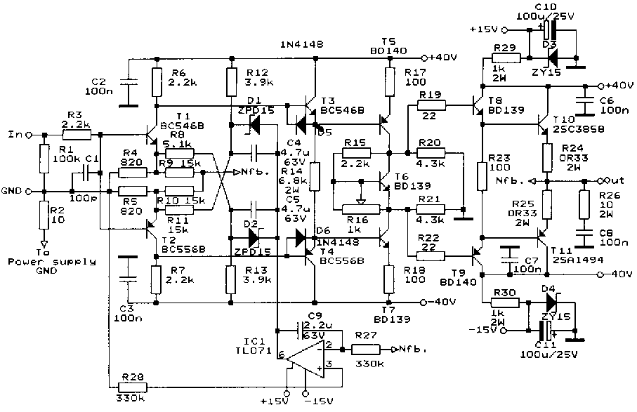
I believe in valves, but I have some friends they believe in transistor. I heard some good ss. amplifiers (Krell, Mark Levinson), and I try to built a good sounding transistor amp. I want to forsake the common design. The schematic:

I don't use long tailed input stage. This amplifier don't need phase splitter as the push-pull valve output stages. Symmetrical complementer common emitter input stage was build here. Zener regulated power supply gives the bias current. I want to build this amp as simple as I can, thats the reason why don't use current source.
The second stage is emitter follower, it gives low impedance driving to high level voltage amplifier. This driving results high speed amplifier, eliminates Miller effect.
Third section is a double common emitter stage, with high bias current. The high current easy to drive the output drivers. R20 and R21 help to exactly determine the amplifiing rates. This resistors eliminates the input impedance changes of the output stage. Output devices made by Sanken, if you have any problem, you can use 2SC3281&2SA1302 from Toshiba.
The fully complementary design help to minimize the distortion without large overall feedback. Strong local feedback used in first and third stages.
The input stage don't eliminate the thermal changes. Simple DC servo circuit added to the circuit. The IC1 work to kill the differences between the GND and the output. The C9 and R27 set the low frequency limit. The servo work very hard. I measure some amplifier
and there was no more than 2mV offset over -10 to +50 degree centigrade. Servo circuit help to forsake the coupling capacitors.
Output power: 40W/ch. If you need more, change the BD139/140 pair to Motorola MJE340/350., then you can use +-65V power supply. It can gives 200W/ch on 8ohm.
You must use more than two output transistors!
I try some square wawe measuring with HP oscilloscope, the output signal was same as the input. The slew rate was more than 60V/us. Frequency response flat from 0.2Hz-1MHz
(without input filter!).
You can improve the sonic performance to use separate transformer for driver stage, and other for output stage. I use 200W transformer for each channel output, and one same 200W transformer for both driver stages. Regulated power supply good for the driver, but not good for output stage.
I try some output bias settings..... Pure class A make very good central heating in my room (need some fun), sound was good. Class AB with 250-300mA is the good choice if you are not cold. There are no significant difference between the settings.
Use heatsinks for T5, T7,T8 and T9, it can be the same as the output
devices heatsink. Put the T6 to the heatsink of the output transistors.
Now I plan to built this amp with MOSFET output stage.
Have a nice listening.
|


